dienelectrics@gmail.com
 0909186879 dienelectrics@gmail.com

A modular cabinet unit solution for high performance applications in industrial mechanical engineering and plant construction is available together with the SINAMICS S120 cabinet modules. The cabinet modules are particularly suited to applications where several drives must work together coordinated. The drive system is thereby normally made up of several motor modules which are connected to the common DC link.
The Motor Modules are in turn powered by a central Line Module.
This kind of configuration allows an interchange of energy between the individual drives, as well as offering a compact and cost-effective design. By this, the power supply is relieved. It is often possible to use Line Modules with a lower rated power than the total power of the connected Motor Modules. This in turn reduces space and expenditure. The SINAMICS S120 cabinet modules also allow to build up single motor drives with greater power outputs. E.g. a 4.5 MW drive with 24-pulse-input can be realized by connecting several Line and Motor Modules.

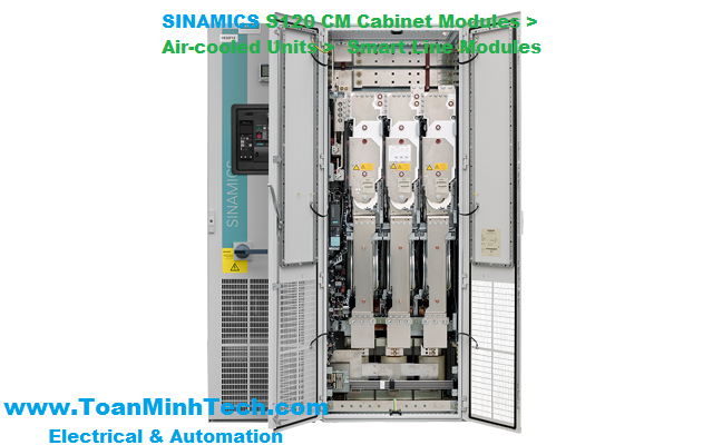
SINAMICS S120 CM Cabinet Modules

SINAMICS S120 CM Cabinet Modules liquid cooled
The SINAMICS S120 cabinet modules system can be supplied for line voltages between 3 AC 380 V - 3 AC 690 V.
The cabinet units offer protection ranging from IP20 to IP54; liquid cooling: up to IP55.
Cooling methods: air and liquid cooling
The following cabinet modules are available at present:
|
Model |
Function |
Power range |
|---|---|---|
|
Motor Modules |
Inverter for the connected motors |
380 - 480 V: 4.8 kW - 800 kW / 3000 kW *) |
|
Basic Line Modules |
6 pulse unregulated supply unit to feed the connected motor modules |
380 - 480 V: 200 kW - 900 kW / 3500 kW *) |
|
Smart Line Modules |
6 pulse regulated supply / regenerative feedback unit to feed the connected motor modules |
380 - 480 V: 250 kW - 800 kW |
|
Active Line Modules |
6 pulse regulated supply / regenerative feedback unit incl. clean power filter to feed the connected motor modules |
380 - 480 V: 132 kW - 900 kW / 3500 kW *) |
|
Braking Modules |
Central brake chopper as cost effective alternative to the regenerative line modules when regenerative operation occurs |
380 - 480 V: 500 kW, 1000 kW |
|
Line Connection Modules |
Power connection module with components attached to the mains, such as load disconnectors i. e. circuit breakers |
380 - 480 V: 250 A - 3200 A |
|
*) Power during parallel connection |
||
|
Model |
Function |
Power range |
|---|---|---|
|
Motor Modules |
Inverter for the connected motors |
380 - 480 V: 110 kW - 800 kW / 3040 kW *) |
|
Basic Line Connection Modules |
6 pulse unregulated supply unit to feed the connected motor modules |
380 - 480 V: 360 kW - 830 kW / 3070 kW *) |
|
Active Line Connection Modules |
6 pulse regulated supply / regenerative feedback unit incl. clean power filter to feed the connected motor modules |
380 - 480 V: 380 kW - 900 kW / 3420 kW *) |
|
Heat Exchanger Modules |
This is used to dissipate the power loss from the liquid-cooled converter. It basically consists of pumps, closed-loop control and a heat exchanger, which means that the inner and outer water cooling circuits are separated from one another. |
400 V / 690 V: 32, 48, 72 und 110 kW Cooling power |
|
*) Power during parallel connection |
||
Further product definitions are in preparation.
Basic Functions: STO, SS1, SBC,
Extended Functions: SLS, SDI, SSM, SLP,SP, SBT, SOS, SS2 (you will find detailed information in the catalog D21.3)
The SINAMICS S120 Cabinet Modules system comprises several individual modules that are perfectly harmonized with one another. Standardized interfaces for the power and communication connections mean that the individual cabinet modules can be combined as required. This allows the user to configure the optimal drive for his application. Not only this, but an extensive range of options allows plant-specific requirements to be very flexibly fulfilled. An extremely compact design and the possibility of pre-configuring the drive system in the plant saves space and minimizes the time and costs associated with installation and commissioning on-site.
Of course, it goes without saying that the cabinet modules also offer the advantages of the SINAMICS S120 Drive System:
- A higher degree of flexibility is achieved by separating the control module and power section.
- Up to 4 vector drives can be connected to one control module. In addition to a safe and cost-saving design, it also allows information to be directly exchanged between the individual drives - therefore relieving the higher-level fieldbus.
- DRIVE-CLiQ, the new interface inside the drive, allows fast and reliable communications between the essential SINAMICS S120 drive components including motors and encoders.
- The PROFIBUS or PROFINET interface integrated as standard allows the SINAMICS S120 Cabinet Modules to be connected to higher-level automation systems such as SIMATIC or SIMOTION.
- The standard and integrated SIZER and STARTER tools provide valuable support when engineering the drive, commissioning it and troubleshooting (diagnostics).
In addition to air cooling, SINAMICS S120 Cabinet Modules are now also available with an innovative liquid-cooled concept.
Liquid cooling facilitates a significantly more efficient heat dissipation, so that it is not necessary to control the climate of rooms. High levels of energy can be saved as a result of the low energy consumption associated with the liquid cooling. In addition to the energy savings as a result of efficient cooling concept, heat can also be recovered. The cooling water that is heated up as part of the cooling process can be used as a source of heat for the process or for heating.
The advantages of liquid cooling for high power ratings when compared to air cooling are the smaller mounting footprint, lower weight and quiet converter operation. It is predestined for applications where space is restricted or poorly ventilated and in harsh environmental conditions, for example onboard ships, in mining and in the industrial environment as a whole.
Configuring a redundant cooling system by using two pumps in the Heat Exchanger Modules is far more cost effective and can be implemented with lower costs when compared to a redundantly configured climate control system. The maintenance work for the units is less as there are no filter mats to replace.
The modular drive system SINAMICS S120 cabinet modules are particularly suitable for drive tasks where several motors work together. Some typical examples of this are:
- Belt conveyors, cranes, ship's drives, test stands, cross cutters, roll changers, roller feeds
- Winders / unwinders, leadind / following drives, calenders, mechanical presses, rolling mill drives
- Branch Chemical Industry
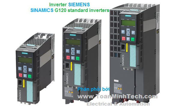
- SINAMICS S120 CM air cooled
for industrial applications
- SINAMICS S120 CM liquid cooled
for industrial applications specially involving drives in harsh environmental conditions, for instance in the process industry, automotive industry, test stands as well as mining
- SINAMICS S120 CM Application Marine Drive
for marine applications with the certificates for the relevant marine classification societies (e.g. DNV-GL, ABS, LR, BV, CCS).
- SINAMICS S120 CM Application Shaft Generator Drive
for the onboard ship supply using shaft-mounted generators and for supplying stand-alone systems (island operation)

SINAMICS S120 Cabinet Modules, air-cooled and liquid-cooled
SINAMICS S120 Cabinet Modules are the components of a modular cabinet system for multi-motor drives with a central supply infeed and a common DC link busbar, as used, for example, in the process industry, automotive industry, metal processing industry as well as in the crane and mining domains. They are available in air-cooled or liquid-cooled versions. As standard, they are installed side by side in a row. Other installation types (e.g. back to back) are possible on request. SINAMICS S120 Cabinet Modules include the chassis units from the SINAMICS S120 series in booksize format (Motor Modules) and chassis format, thus making the range an ideal supplement to the SINAMICS G150 and SINAMICS S150 cabinet converter series for single-motor drives.
All drive components, from the supply infeed to the motor-side inverters, are configured in a clear, compact layout in the individual Cabinet Modules. They can be flexibly combined and optimally adapted to customer-specific requirements thanks to a comprehensive array of options.
The main components of the air-cooled system are as follows:
The main components of the liquid-cooled system are as follows:
Standardized interfaces for both the power and the control connections facilitate engineering and installation. Communication between the power modules and the central Control Unit takes place via DRIVE‑CLiQ, the internal drive serial interface.

Example of a drive line-up with SINAMICS S120 Cabinet Modules for a multi-motor drive
The following tables provide an overview of the voltage ranges and power ratings of the available SINAMICS S120 Cabinet Modules.
Voltage ranges and powers for air-cooled SINAMICS S120 Cabinet Modules
|
|
Line voltage |
Input current |
DC link voltage |
DC link current |
Output current |
Power range of single modules |
|---|---|---|---|---|---|---|
|
Line Connection Modules 1) |
380 ... 480 V 3 AC |
250 ... 3200 A |
– |
– |
– |
– |
|
500 ... 690 V 3 AC |
280 ... 3200 A |
– |
– |
– |
– |
|
|
Basic Line Modules 1) |
380 ... 480 V 3 AC |
365 ... 1630 A |
510 ... 650 V |
420 ... 1880 A |
– |
200 ... 900 kW |
|
500 ... 690 V 3 AC |
260 ... 1580 A |
675 ... 930 V |
300 ... 1880 A |
– |
250 ... 1500 kW |
|
|
Smart Line Modules 1) |
380 ... 480 V 3 AC |
463 ... 1430 A |
510 ... 650 V |
550 ... 1700 A |
– |
250 ... 800 kW |
|
500 ... 690 V 3 AC |
463 ... 1430 A |
675 ... 930 V |
550 ... 1700 A |
– |
450 ... 1400 kW |
|
|
Active Line Modules 1) |
380 ... 480 V 3 AC |
210 ... 1405 A |
540 ... 720 V |
235 … 1574 A |
– |
132 ... 900 kW |
|
500 ... 690 V 3 AC |
575 ... 1270 A |
710 ... 1035 V |
644 ... 1422 A |
– |
560 ... 1400 kW |
|
|
Motor Modules booksize |
380 ... 480 V 3 AC |
– |
510 ... 720 V |
– |
9 ... 132 A |
4.8 ... 71 kW |
|
Motor Modules chassis 1) |
380 ... 480 V 3 AC |
– |
510 ... 720 V |
– |
210 ... 1405 A |
110 ... 800 kW |
|
500 ... 690 V 3 AC |
– |
675 ... 1035 V |
– |
85 ... 1270 A |
75 ... 1200 kW |
|
|
Central Braking Modules 1) |
380 ... 480 V 3 AC |
– |
510 ... 720 V |
– |
– |
500 ... 1000 kW |
|
500 … 600 V 3 AC |
– |
675 ... 900 V |
– |
– |
550 ... 1100 kW |
|
|
660 … 690 V 3 AC |
– |
890 ... 1035 V |
– |
– |
630 ... 1200 kW |
|
|
Auxiliary Power Supply Modules |
380 ... 690 V 3 AC |
125 ... 250 A |
– |
– |
– |
– |
1) The power can be increased by connecting up to four identical modules in parallel.
Voltage ranges and power ratings for liquid-cooled SINAMICS S120 Cabinet Modules
|
|
Line voltage |
Input current |
DC link voltage |
DC link current |
Output current |
Power range of single modules |
|---|---|---|---|---|---|---|
|
Basic Line Connection Modules 1) |
380 ... 480 V 3 AC |
610 ... 1420 A |
510 ... 650 V |
740 ... 1730 A |
– |
360 ... 830 kW |
|
500 ... 690 V 3 AC |
340 ... 1350 A |
675 ... 930 V |
420 ... 1650 A |
– |
355 ... 1370 kW |
|
|
Active Line Connection Modules 1) |
380 ... 480 V 3 AC |
985 ... 1405 A |
540 ... 720 V |
1100 ... 1573 A |
– |
630 ... 900 kW |
|
500 ... 690 V 3 AC |
1025 ... 1560 A |
710 ... 1035 V |
1147 ... 1740 A |
– |
1100 ... 1700 kW |
|
|
Motor Modules 1) |
380 ... 480 V 3 AC |
– |
510 ... 720 V |
– |
605 ... 1405 A |
315 ... 800 kW |
|
500 ... 690 V 3 AC |
– |
675 ... 1035 V |
– |
465 ... 1560 A |
450 ... 1500 kW |
1) The power can be increased by connecting up to four identical modules in parallel.
The outstanding system features of the SINAMICS S120 Cabinet Modules provide the following advantages:
- Process optimization with minimum outlay + A standard PROFIBUS or PROFINET interface and various analog and digital interfaces enables easy integration into automation solutionsSINAMICS S120 Cabinet Modules have been specially developed to allow simple configuration of multi-motor systems. They are used for applications where several motors must be coordinated to realize a drive task as multi-motor drives in a drive line-up. Examples of such applications include:
- Packaging machines
High-power single drives (parallel connection) can also be implemented with Cabinet Modules.
They have been designed according to the zone concept principle and therefore offer the highest possible level of operational reliability. EMC measures have been rigorously implemented. With the help of simulated conditions, partitions have been designed to act as air guides and heat dissipation units.
Special measures used in the construction of the cabinets ensure that they remain mechanically durable over their entire life cycle.
Attention has been paid to providing a wide range of cable routing options and special design concepts are applied consistently to broaden the scope of application and simplify service. The units have all the necessary connections and connecting elements. Thanks to their carefully considered configuration concept, cabinets are shipped in a ready-to-connect state or, in the case of multiple transport units, have been prepared for quick assembly. An extensive spectrum of options designed to adapt the units to a variety of different applications facilitates the selection process.
All components, from individual parts to the ready-to-connect cabinet, undergo rigorous testing throughout the entire production process. This guarantees a high level of functional reliability during installation and commissioning, as well as in operation.
Replaceable components have been designed so that they can be quickly and easily replaced. In addition, the "Spares On Web" Internet tool makes it easy to view the spare parts that are available for the particular order at all times 1).
1) The properties of the SINAMICS S120 Cabinet Modules described in this catalog are not transferable to cabinet units constructed to meet the requirements of specific applications.
Line Modules are coupled with the various Motor Modules by means of prefabricated busbar sets with different current carrying capacities.
All standard busbars, as well as electronics components, are protected against environmental influences. This is achieved through the use of nickel-plated copper bars and painted modules throughout.
A special, standard auxiliary power supply system supplies the individual Cabinet Modules with the required auxiliary voltages for the power components, fans and 24 V loads.
These voltages are preferably generated using an auxiliary power supply module. Additional supply possibilities are available using the K76 option (auxiliary power supply generation in the Line Connection Module) or using an external supply in the auxiliary power supply system.
The auxiliary power supply system comprises an auxiliary power supply module with two terminal blocks (air cooling) and one auxiliary voltage terminal (liquid cooling) and a 24 V DC fuse as well as the required connecting cables. It is supplied completely assembled and ready to operate. Only the cable connections to the adjacent Cabinet Module must be established on-site.
Communication between the Control Unit, power units and other active SINAMICS components is realized via DRIVE‑CLiQ connections.
DRIVE‑CLiQ is an internal serial interface of the drive that enables fast and easy configuration of the complete drive line-up with prefabricated cables in varying lengths.
The Cabinet Modules can be optionally supplied in pre-configured transport units up to a total length of 2400 mm. This option is particularly recommended in air-cooled Cabinet Modules for Line Modules together with Line Connection Modules since, in this case, the Line Connection Module must be equipped with a pre-charging DC link or line reactors (depending on the type of Line Module), in addition to the electrical interface (busbar). For liquid-cooled Cabinet Modules, delivery in transport units has the advantage that the tube system of the cooling system can be implemented completely without couplings. Transport units thus enable the various devices to be quickly and easily assembled on-site.
The following devices are equipped with coated modules as standard:
- Booksize format units
The coating on the modules protects the sensitive SMD components against corrosive gases, chemically active dust and moisture.
All of the copper busbars used in the converter cabinets are nickel-plated to achieve the best possible immunity to environmental effects. Furthermore, there is no need to clean the contacts on the customer terminals as otherwise required for bare copper connections.
Note:
With some options, parts of the copper busbars cannot be nickel-plated for technical reasons.
The Cabinet Modules are delivered with a PE bar as standard. It is used to connect and fasten PE conductors.
The EN 60529 standard covers the protection of electrical equipment by means of housings, covers or equivalent, and includes:
- Protection of persons against accidental contact with live or moving parts within the housing and protection of the equipment against the ingress of solid foreign bodies (touch protection and protection against ingress of solid foreign bodies)
The degrees of protection are specified by abbreviations comprising the code letters IP and two digits.
|
Degree of protection |
First code number (touch protection and protection against solid foreign bodies) |
Second code number (protection of the equipment against the ingress of water) |
|---|---|---|
|
IP20 |
Protected against solid foreign bodies |
No water protection |
|
IP21 |
Protected against solid foreign bodies |
Protected against drip water Vertically falling water drops shall not have a harmful effect. |
|
IP23 (Option M23) |
Protected against solid foreign bodies |
Protected against spray water Water sprayed on both sides of the vertical at an angle of up to 60° shall not have a harmful effect. |
|
IP43 (Option M43) |
Protected against solid foreign bodies |
Protected against spray water Water sprayed on both sides of the vertical at an angle of up to 60° shall not have a harmful effect. |
|
IP54 (Option M54) |
Dust protected Ingress of dust is not totally prevented, but dust must not be allowed to enter in such quantities that the functioning or safety of the equipment is impaired. Complete touch protection |
Protected against splash water Water splashing onto the enclosure from any direction shall not have a harmful effect. |
|
IP55 (Option M55) |
Dust protected Ingress of dust is not totally prevented, but dust must not be allowed to enter in such quantities that the functioning or safety of the equipment is impaired. Complete touch protection |
Protected against water jet (nozzle) Water projected by a nozzle against the enclosure from any direction shall not have a harmful effect. |
Air-cooled Cabinet Modules meet degree of protection IP20, liquid-cooled Cabinet Modules degree of protection IP21, as standard. The other degrees of protection outlined here are available as an option.
As the customer interface to the control system, a PROFIBUS interface is available on the CU320-2 DP Control Unit or a PROFINET interface on the CU320-2 PN Control Unit as standard.
In the case of the air-cooled Cabinet Modules, the inputs and outputs available as standard on the customer terminal block -X55, which are easy to access and easy to connect up, can be provided.
In the case of the liquid-cooled Cabinet Modules, the components are directly connected.
For further information, please refer to the SINAMICS Low Voltage Engineering Manual.
SINAMICS S120 can use a dynamic, high-precision closed-loop vector control (drive object type VECTOR), or a highly dynamic closed-loop servo control (drive object type SERVO).
The software functions available as standard are described below:
|
Software and protective functions |
Description |
|---|---|
|
Setpoint input |
The setpoint can be specified both internally and externally; internally as a fixed setpoint, motorized potentiometer setpoint or jog setpoint, externally via the communications interface or an analog input. The internal fixed setpoint and the motorized potentiometer setpoint can be switched or adjusted via control commands from any interface. |
|
Motor identification |
The automatic motor identification function makes commissioning faster and easier and optimizes closed-loop control of the drive. |
|
Ramp-function generator |
A user-friendly ramp-function generator with separately adjustable ramp-up and ramp-down times, together with adjustable rounding times in the lower and upper speed ranges, allows the drive to be smoothly accelerated and braked. This results in a good speed control response and plays its role in reducing the stress on the mechanical system. The down ramp can be parameterized separately for a quick stop. |
|
Vdc max controller |
The Vdc max controller automatically prevents overvoltages in the DC link, if the set down ramp is too short, for example. This may also extend the set ramp-down time. Note: This function only makes sense for single-axis applications. |
|
Kinetic buffering (KIP) |
For brief line supply failures, the kinetic energy of the rotating drive is used to buffer the DC link and therefore prevents fault trips. The drive converter remains operational as long as the drive can provide regenerative energy as a result of its motion and the DC link voltage does not drop below the shutdown threshold. When the line supply recovers within this time, the drive is again bumplessly accelerated up to its setpoint speed. |
|
Automatic restart |
The automatic restart switches the drive on again when the power is restored after a power failure, and ramps up to the current speed setpoint. |
|
Flying restart |
The flying restart function allows the converter to be switched to a motor that is still turning. With the voltage sensing capability provided by the optional VSM10, the flying restart time for large induction motors can be significantly reduced because the motor does not need to be de-magnetized. |
|
Technology controller |
Using the technology controller (PID controller) function module, level or flow controls and complex tension controls can be implemented, for example. The existing D component can act both on the system deviation well as on the actual value (factory setting). The P, I, and D components are set separately. |
|
Free function blocks |
Using the freely programmable function blocks, it is easy to implement logic and arithmetic functions for controlling the SINAMICS drive. The blocks can be programmed at the operator panel or the STARTER commissioning tool. |
|
Drive Control Chart (DCC) |
Drive Control Chart (DCC) is an additional tool for the easy configuration of technological functions for SINAMICS. The block library contains a large selection of control, arithmetic and logic blocks as well as extensive open-loop and closed-loop control functions. The user-friendly DCC editor enables easy graphics-based configuration, allows control loop structures to be clearly represented and provides a high degree of reusability of charts that have already been created. DCC is an add-on for the STARTER commissioning tool (→ Tools and Engineering). |
|
I2t sensing for motor protection |
A motor model stored in the converter software calculates the motor temperature based on the current speed and load. More exact measurement of the temperature, which also takes into account the influence of the ambient temperature, is possible by means of direct temperature measurement using KTY84 sensors in the motor winding. |
|
Motor temperature evaluation |
Motor protection by evaluating a KTY84, PTC or Pt100 temperature sensor. When a KTY84 temperature sensor is connected, the limit values can be set for alarm or shutdown. When a PTC thermistor is connected, the system reaction to triggering of the thermistor (alarm or trip) can be defined. |
|
Motor blocking protection |
A blocked motor is detected and protected against thermal overloading by a fault trip. |
|
Brake control |
“Simple brake control” for controlling holding brakes: The "extended braking control" function module allows complex braking control, for example, for motor holding brakes and operational brakes. |
|
Write protection |
Write protection to prevent unintentional changing of the setting parameters (without password function). |
|
Know-how protection |
Know‑how protection for encrypting stored data, e.g. to protect expert configuring knowledge, and to protect against modification and duplication (with password function). |
|
Web server |
The integrated web server provides information about the drive unit via its web pages. The web server is accessed using a web browser via unsecured (http) or secured transfer protocol (https). |
|
Power unit protection |
Description |
|---|---|
|
Ground fault monitoring at the output |
A ground fault at the output is detected by a total current monitor and results in shutdown in grounded systems. |
|
Electronic short-circuit protection at the output |
A short-circuit at the output (e.g. at the converter output terminals, in the motor cable or in the motor terminal box) is detected and the converter shuts down with a "fault". |
|
Thermal overload protection |
An alarm is issued first when the overtemperature threshold responds. If the temperature continues to rise, the unit either shuts down or independently adjusts the pulse frequency or output current so that thermal load is reduced. Once the cause of the fault has been eliminated (e.g. cooling has been improved), the original operating values are automatically resumed. |
The most important directives and standards are listed below. These are used as basis for the SINAMICS S120 Cabinet Modules and they must be carefully observed to achieve an EMC-compliant configuration that is safe both in terms of functionally and in operation.
|
European directives |
|
|---|---|
|
2006/95/EC |
Low Voltage Directive: |
|
2004/108/EC |
EMC directive: |
|
2006/42/EC |
Machinery Directive: |
|
European standards |
|
|
EN ISO 3744 |
Acoustics - Determination of sound power levels and sound energy levels of noise sources using sound pressure – Engineering methods for an essentially free acoustic field over a reflecting plane |
|
EN ISO 13849‑1 |
Safety of machinery – safety-related parts of control systems; |
|
EN 60146‑1‑1 |
Semiconductor converters – General requirements and line-commutated converters |
|
EN 60204‑1 |
Safety of machinery – Electrical equipment of machines; |
|
EN 60529 |
Degrees of protection provided by enclosures (IP Code) |
|
EN 61508‑1 |
Functional safety of electrical/electronic/programmable electronic safety-related systems |
|
EN 61800‑2 |
Adjustable speed electrical power drive systems |
|
EN 61800‑3 |
Adjustable speed electrical power drive systems |
|
EN 61800‑5‑1 |
Adjustable speed electrical power drive systems |
|
EN 61800‑5‑2 |
Adjustable speed electrical power drive systems |
Power is fed to the drive line-up via Line Modules, which generate a DC voltage from the line voltage and, therefore, supply energy to the Motor Modules connected to the DC link. They are suitable for connection to grounded TN/TT and non-grounded IT systems.
The Line Modules are connected to the line supply system via Line Connection Modules and are equipped as standard according to Category C3. Category C3 is part of the "second environment" (in accordance with EN 61800-3). The “second environment” constitutes locations outside residential areas or industrial sites which are supplied from the medium-voltage network via a separate transformer.
The range of Line Modules has power ratings from 132 kW to 900 kW (380 V to 480 V) and from 250 kW to 1500 kW (500 V to 690 V). Furthermore, up to four identical Line Modules can be connected in parallel in order to increase the power rating.
For a compact configuration, Line Connection Modules up to input currents of 3200 A are available. Two Line Modules can be operated in parallel on these Line Connection Modules.
The following types of Line Module are available:
Basic Line Modules
Basic Line Modules are designed only for infeed operation, i.e. they are not capable of recovering energy to the line supply.
If regenerative energy is produced, e.g. when the drives brake, then it must be converted to heat by means of a Braking Module and a braking resistor.
When a Basic Line Module is used as the infeed, a line reactor appropriate to the supply conditions must be installed. Line reactors are generally required if two or more Basic Line Modules are operated in parallel on a common supply system in order to increase power.
For this reason, line reactors are installed in the appropriate Line Connection Module as standard.

Line Connection Module with Basic Line Module ≤800 A

Line Connection Module with Basic Line Module >800 A
If, for example, a converter transformer is used to connect to the line supply (12-pulse operation), it may be possible to omit line reactors (depending on the supply conditions on site) and they can be optionally deselected (option L22 for a Line Connection Module combined with a Basic Line Module).
For a compact configuration, Line Connection Modules with input currents of up to 3200 A are available. Two Basic Line Modules can be operated in parallel on these Line Connection Modules. Versions with line-side fuses are available for parallel connections in order to provide selective protection of the individual Basic Line Modules.

Line Connection Module with Basic Line Modules connected in parallel
Smart Line Modules
Smart Line Modules can supply energy to the DC link and return regenerative energy to the supply system. Braking Modules and braking resistors are required only if the drives need to be decelerated in a controlled manner after a power failure (i.e. when energy cannot be recovered to the supply). When a Smart Line Module is used as the infeed, the necessary line reactor is included in the device as standard and can be optionally deselected (option L22).

Line Connection Module with Smart Line Module ≤800 A

Line Connection Module with Smart Line Module >800 A

Line Connection Module with Smart Line Modules connected in parallel
Active Line Modules
Active Line Modules can supply energy to the DC link and return regenerative energy to the supply system. Braking Modules and braking resistors are required only if the drives need to be decelerated in a controlled manner after a power failure (i.e. when energy cannot be recovered to the supply).
In contrast to Basic Line Modules and Smart Line Modules, however, Active Line Modules generate a regulated DC voltage which remains constant despite fluctuations in the line voltage. However, in this case, the line voltage must remain within the permissible tolerance range. Active Line Modules draw a virtually sinusoidal current from the supply which limits any harmful harmonics.
Active Line Modules must always be used in conjunction with an Active Interface Module. Active Interface Modules include the required pre-charging circuit for the Active Line Module in addition to a Clean Power Filter. For SINAMICS S120 Cabinet Modules, these two components are always regarded as a single unit.

Line Connection Module with Active Interface Module and Active Line Module ≤ 800 A (example frame size HX + HI)

Line Connection Module with Active Interface Module and Active Line Module >800 A
In the example, two units comprising an Active Interface Module and Active Line Module are connected in parallel to jointly supply the DC link.

Line Connection Module with Active Interface Modules and Active Line Modules connected in parallel
Braking Modules enable braking resistors to absorb the regenerative energy produced during drive deceleration, which is then converted into heat. Using a Braking Module and a braking resistor, it is possible to brake motors even when the power fails.
Braking Modules as a Line Module or Motor Module option
For lower braking powers, Braking Modules are available with continuous braking powers up to 50 kW. These Braking Modules are ordered as an option for the Line Modules and Motor Modules (order codes L61/L64 (25 kW) or L62/L65(50 kW), refer to the option description).
Central Braking Modules
For higher continuous braking powers, separate Central Braking Modules are available. These modules are used centrally in the drive line-up. To increase the braking power, up to four Central Braking Modules can be connected in parallel.
There are two different types of Motor Module available with the SINAMICS S120 Cabinet Modules drive system.
Booksize Base Cabinets with Booksize Cabinet Kits
Motor Modules at the low end of the power range from 4.8 kW to 71 kW (380 V to 480 V) can be implemented as Booksize Cabinet Kits installed in Booksize Base Cabinets.
Chassis Cabinets
Each Chassis Cabinet is fitted with one SINAMICS S120 Motor Module in chassis format and covers the power range from 75 kW to 1200 kW (380 V to 480 V or 500 V to 690 V). The power rating can be extended up to approx. 4500 kW by connecting up to four Motor Modules in the chassis format in parallel.
SINAMICS S120 Motor Modules in chassis format can also be used as a Braking Module (braking chopper) if a 3-phase braking resistor is connected instead of a motor.
For more information on this topic, please refer to the SINAMICS Low Voltage Engineering Manual.
Auxiliary Power Supply Modules supply power to the auxiliary power supply system of the SINAMICS S120 Cabinet Modules.
Units connected to this auxiliary power supply system include the fans of the SINAMICS S120 devices installed in the Cabinet Modules. In addition, the auxiliary power supply system supplies the electronic modules with an external 24 V DC voltage. This is required when the DC link is not charged, for instance, in order to maintain PROFIBUS or PROFINET communication.
|
Electrical specifications |
|||
|---|---|---|---|
|
Line voltages |
380 ... 480 V 3 AC, ±10 % (-15 % <1 min) 500 … 690 V 3 AC, ±10 % (-15 % <1 min) |
||
|
Line supply types |
Grounded TN/TT systems and non-grounded IT systems |
||
|
Line frequency |
47 ... 63 Hz |
||
|
Output frequency 1) |
|
||
|
0 ... 550 Hz |
||
|
0 ... 550 Hz |
||
|
0 ... 550 Hz |
||
|
Line power factor |
|
||
|
>0.96 |
||
|
>0.96 |
||
|
Adjustable (factory-set to cos φ = 1) |
||
|
Efficiency |
|
||
|
>99 % |
||
|
>98.5 % |
||
|
>97.5 % (including Active Interface Module) |
||
|
>98.5 % |
||
|
Overvoltage category |
III to EN 61800‑5‑1 |
||
|
Control method |
Vector/Servo control with and without encoder or V/f control |
||
|
Fixed speeds |
15 fixed speeds plus 1 minimum speed, parameterizable (in the default setting, 3 fixed setpoints plus 1 minimum speed are selectable using terminal block/PROFIBUS/PROFINET) |
||
|
Skippable speed ranges |
4, parameterizable |
||
|
Setpoint resolution |
0.001 rpm digital (14 bits + sign) |
||
|
Braking operation |
With Active Line Modules and Smart Line Modules, four-quadrant operation as standard (energy recovery). |
||
|
Cabinet system |
|||
|
Cabinet system |
Rittal TS 8, doors with double-bit key, three-section base plates for cable entry |
||
|
Paint finish |
RAL 7035 (indoor requirements) |
||
|
Mechanical specifications |
|||
|
Degree of protection |
IP20 (higher degrees of protection up to IP54 optional) |
||
|
Protection class |
I acc. to EN 61800‑5‑1 |
||
|
Touch protection |
EN 50274/BGV A3 for the intended purpose |
||
|
Cooling method |
Forced air cooling AF according to EN 60146 |
||
|
Ambient conditions |
Storage 2) |
Transport 2) |
Operation |
|
Ambient temperature |
-25 ... +55 °C |
-25 ... +70 °C |
0 ... +40 °C |
|
Relative humidity (condensation not permissible) |
5 ... 95 % |
5 ... 95 % at 40 °C |
5 ... 95 % |
|
Environmental class/harmful chemical substances |
Class 1C2 |
Class 2C2 |
Class 3C2 |
|
Organic/biological influences |
Class 1B1 |
Class 2B1 |
Class 3B1 |
|
Degree of pollution |
2 acc. to EN 61800‑5‑1 |
||
|
Installation altitude |
Cabinet Modules chassis format: For Booksize Cabinet Kit format Motor Modules as well as Central Braking Modules: |
||
|
Mechanical stability |
Storage 2) |
Transport 2) |
Operation |
|
Vibration load |
Class 1M2 |
Class 2M2 |
– |
|
1.5 mm at 5 ... 9 Hz |
3.1 mm at 5 ... 9 Hz |
0.075 mm at 10 ... 58 Hz |
|
5 m/s² at >9 ... 200 Hz |
10 m/s² at >9 ... 200 Hz |
9.8 m/s² at >58 ... 200 Hz |
|
Shock load |
Class 1M2 |
Class 2M2 |
Class 3M4 |
|
40 m/s² at 22 ms |
100 m/s² at 11 ms |
100 m/s² at 11 ms |
|
Compliance with standards |
|||
|
Conformances/approvals, according to |
CE (EMC Directive No. 2004/108/EC and Low Voltage Directive No. 2006/95/EC and Machinery Directive 2006/42/EC for functional safety) |
||
|
Radio interference suppression |
SINAMICS drive converter systems are not designed for connection to the public grid (first environment). Radio interference suppression is compliant with the EMC product standard for variable-speed drives EN 61800‑3, "Second environment" (industrial networks). EMC disturbances can occur when connected to the public power networks. However, if additional measures are taken (e.g. → line filter), it can also be operated in the "first environment". |
||
1) Higher output frequencies available on request.
2) In transport packaging.
Deviations from the specified class are underlined.
SINAMICS S120 Cabinet Modules and the associated system components are rated for an ambient temperature of 40 °C and installation altitudes up to 2000 m above sea level.
At ambient temperatures > 40 °C, the output current must be reduced. Ambient temperatures above 50 °C are not permissible.
At installation altitudes > 2000 m above sea level, it must be taken into account that the air pressure, and therefore air density, decreases as the height increases. As a consequence, the cooling efficiency and the insulation capacity of the air also decrease.
Due to the reduced cooling efficiency, it is necessary to both reduce the ambient temperature and lower heat loss in the Cabinet Module by reducing the output current, whereby ambient temperatures lower than 40 °C may be offset to compensate.
The following table specifies the permissible output currents as a function of the installation altitude and ambient temperature for the various degrees of protection. (The permissible compensation between installation altitude and the ambient temperatures < 40 °C – air intake temperature at the entry to the Cabinet Module – has been taken into account in the specified values.)
The values apply under the precondition that it is guaranteed that the cooling air, as specified in the technical data, flows through the units as a result of the cabinet arrangement.
As additional measure for installation altitudes from 2000 m up to 5000 m, an isolating transformer is required in order to reduce transient overvoltages according to EN 60664‑1.
For additional information, please refer to the SINAMICS Low Voltage Engineering Manual.
Current-derating factors for Cabinet Modules as a function of the ambient/air intake temperature, the installation altitude and the degree of protection.
|
Degree of protection |
Installation altitude above sea level |
Current derating factor (as a percentage of the rated current) |
||||||
|---|---|---|---|---|---|---|---|---|
|
|
m |
20 °C |
25 °C |
30 °C |
35 °C |
40 °C |
45 °C |
50 °C |
|
IP20, IP21, IP23, IP43 |
0 ... 2000 |
100 % |
100 % |
100 % |
100 % |
100 % |
93.3 % |
86.7 % |
|
2001 ... 2500 |
100 % |
100 % |
100 % |
100 % |
96.3 % |
|
|
|
|
2501 ... 3000 |
100 % |
100 % |
100 % |
98.7 % |
|
|
|
|
|
3001 ... 3500 |
100 % |
100 % |
100 % |
|
|
|
|
|
|
3501 ... 4000 |
100 % |
100 % |
96.3 % |
|
|
|
|
|
|
4001 ... 4500 |
100 % |
97.5 % |
|
|
|
|
|
|
|
4501 ... 5000 |
98.2 % |
|
|
|
|
|
|
|
|
IP54 |
0 ... 2000 |
100 % |
100 % |
100 % |
100 % |
93.3 % |
86.7 % |
80 % |
|
2001 ... 2500 |
100 % |
100 % |
100 % |
96.3 % |
89.8 % |
|
|
|
|
2501 ... 3000 |
100 % |
100 % |
98.7 % |
92.5 % |
|
|
|
|
|
3001 ... 3500 |
100 % |
100 % |
94.7 % |
|
|
|
|
|
|
3501 ... 4000 |
100 % |
96.3 % |
90.7 % |
|
|
|
|
|
|
4001 ... 4500 |
97.5 % |
92.1 % |
|
|
|
|
|
|
|
4501 ... 5000 |
93 % |
|
|
|
|
|
|
|
Current derating for SINAMICS S120 Motor Modules, chassis format as a function of the pulse frequency
To reduce motor noise or to increase output frequency, the pulse frequency can be increased relative to the factory setting (1.25 kHz or 2 kHz). When the pulse frequency is increased, the derating factor of the output current must be taken into account. This derating factor must be applied to the currents specified in the technical specifications.
Further information is provided in the SINAMICS Low Voltage Engineering Manual.
Derating factor of the output current as a function of the pulse frequency for units with a rated pulse frequency of 2 kHz
|
Motor Module in chassis format |
Type rating |
Output current |
Derating factor at pulse frequency |
||||
|---|---|---|---|---|---|---|---|
|
6SL3720-... |
kW |
A |
2.5 kHz |
4 kHz |
5 kHz |
7.5 kHz |
8 kHz |
|
380 ... 480 V 3 AC |
|||||||
|
1TE32-1AA3 |
110 |
210 |
95 % |
82 % |
74 % |
54 % |
50 % |
|
1TE32-6AA3 |
132 |
260 |
95 % |
83 % |
74 % |
54 % |
50 % |
|
1TE33-1AA3 |
160 |
310 |
97 % |
88 % |
78 % |
54 % |
50 % |
|
1TE33-8AA3 |
200 |
380 |
96 % |
87 % |
77 % |
54 % |
50 % |
|
1TE35-0AA3 |
250 |
490 |
94 % |
78 % |
71 % |
53 % |
50 % |
Derating factor of the output current as a function of the pulse frequency for units with a rated pulse frequency of 1.25 kHz
|
Motor Module in chassis format |
Type rating |
Output current |
Derating factor at pulse frequency |
||||
|---|---|---|---|---|---|---|---|
|
6SL3720-... |
kW |
A |
2 kHz |
2.5 kHz |
4 kHz |
5 kHz |
7.5 kHz |
|
380 ... 480 V 3 AC |
|||||||
|
1TE36-1AA3 |
315 |
605 |
83 % |
72 % |
64 % |
60 % |
40 % |
|
1TE37-5AA3 |
400 |
745 |
83 % |
72 % |
64 % |
60 % |
40 % |
|
1TE38-4AA3 |
450 |
840 |
87 % |
79 % |
64 % |
55 % |
40 % |
|
1TE41-0AA3 |
560 |
985 |
92 % |
87 % |
70 % |
60 % |
50 % |
|
1TE41-2AA3 |
710 |
1260 |
92 % |
87 % |
70 % |
60 % |
50 % |
|
1TE41-4AA3 |
800 |
1405 |
97 % |
95 % |
74 % |
60 % |
50 % |
|
500 ... 690 V 3 AC |
|||||||
|
1TG28-5AA3 |
75 |
85 |
93 % |
89 % |
71 % |
60 % |
40 % |
|
1TG31-0AA3 |
90 |
100 |
92 % |
88 % |
71 % |
60 % |
40 % |
|
1TG31-2AA3 |
110 |
120 |
92 % |
88 % |
71 % |
60 % |
40 % |
|
1TG31-5AA3 |
132 |
150 |
90 % |
84 % |
66 % |
55 % |
35 % |
|
1TG31-8AA3 |
160 |
175 |
92 % |
87 % |
70 % |
60 % |
40 % |
|
1TG32-2AA3 |
200 |
215 |
92 % |
87 % |
70 % |
60 % |
40 % |
|
1TG32-6AA3 |
250 |
260 |
92 % |
88 % |
71 % |
60 % |
40 % |
|
1TG33-3AA3 |
315 |
330 |
89 % |
82 % |
65 % |
55 % |
40 % |
|
1TG34-1AA3 |
400 |
410 |
89 % |
82 % |
65 % |
55 % |
35 % |
|
1TG34-7AA3 |
450 |
465 |
92 % |
87 % |
67 % |
55 % |
35 % |
|
1TG35-8AA3 |
560 |
575 |
91 % |
85 % |
64 % |
50 % |
35 % |
|
1TG37-4AA3 |
710 |
735 |
87 % |
79 % |
64 % |
55 % |
25 % |
|
1TG38-1AA3 |
800 |
810 |
97 % |
95 % |
71 % |
55 % |
35 % |
|
1TG38-8AA3 |
900 |
910 |
92 % |
87 % |
67 % |
55 % |
33 % |
|
1TG41-0AA3 |
1000 |
1025 |
91 % |
86 % |
64 % |
50 % |
30 % |
|
1TG41-3AA3 |
1200 |
1270 |
87 % |
79 % |
55 % |
40 % |
25 % |
The following tables list the maximum achievable output frequency as a function of the pulse frequency:
Maximum output frequencies achieved by increasing the pulse frequency in Vector mode
|
Pulse frequency |
Max. achievable output frequency |
|---|---|
|
1.25 kHz |
100 Hz |
|
2 kHz |
160 Hz |
|
2.5 kHz |
200 Hz |
|
4 kHz |
300 Hz |
Maximum output frequencies achieved by increasing the pulse frequency in Servo mode
|
Pulse frequency |
Max. achievable output frequency |
|---|---|
|
2 kHz |
300 Hz |
|
4 kHz |
300/550 Hz 1) |
1) Higher frequencies on request.
SINAMICS S120 Cabinet Modules with power units in booksize format and the associated system components are rated for an ambient temperature of 40 °C and installation altitudes up to 1000 m above sea level. If SINAMICS S120 Cabinet Modules with power units in booksize format are operated at ambient temperatures higher than 40 °C and/or installation altitudes higher than 1000 m above sea level, then the corresponding derating functions must be taken into account as a function of the ambient temperature and/or the installation altitude. These derating factors are different from the derating factors for the chassis format power units and are listed in Catalog PM 21.
SINAMICS S120 Cabinet Modules have an overload reserve, e.g. to handle breakaway torques. If larger surge loads occur, this must be taken into account when configuring. For drives with overload requirements, the appropriate base load current must, therefore, be used as a basis for the required load.
Permissible overload assumes that the drive converter is operated at its base-load current before and after the overload occurs, based on a duty cycle duration of 300 s.
For temporary, periodic duty cycles with high variations of load within the duty cycle, the relevant sections of the SINAMICS Low Voltage Engineering Manual must be observed.
Motor Modules in chassis format
Motor Modules with power units in the chassis format can be configured on the basis of different base load currents.
The base-load current for a low overload IL is the basis for a duty cycle of 110 % for 60 s or 150 % for 10 s.

Low overload
The base-load current IH for a high overload is based on a load cycle of 150 % for 60 s or 160 % for 10 s.

High overload
Motor Modules in booksize format
Motor Modules with power units in the booksize format have the following overload capabilities:

High overload
Line Modules in chassis format
The base-load current for a high overload IH DC is the basis for a duty cycle of 150 % for 60 s or Imax DC for 5 s.


Smart Line Modules are non-regulated rectifier/regenerative units. The infeed occurs over a diode jumper, while stable, line-commutated regenerative feedback takes place via IGBTs with 100 % continuous energy regeneration. An autotransformer is not required for regenerative feedback.
The regenerative capability can be deactivated.
Smart Line Modules are suitable for connection to grounded TN/TT and non-grounded IT systems. The following voltages and power ratings are available:
|
Line voltage |
Rated power |
|---|---|
|
380 ... 480 V 3 AC |
250 ... 800 kW |
|
500 ... 690 V 3 AC |
450 ... 1400 kW |
The power ratings can be increased by connecting up to four identical Smart Line Modules in parallel.
For additional information, please refer to the SINAMICS Low Voltage Engineering Manual.
IGBTs (fundamental frequency-switched) serve as Smart Line Module power semiconductors. Because this reduces switching losses, a high percentage of the power unit current can be utilized.
The current flows in the direction of the infeed via the freewheeling diodes of the IGBTs. This means that the Smart Line Module behaves in a similar way to the Basic Line Module. If the DC link voltage increases due to regenerative operation of the drives, the IGBTs conduct the current, thus feeding the energy back into the supply system.
In contrast to Active Line Modules, Smart Line Modules do not require a line-side filter; all they require is a line reactor (4 % uk). The unit has a built-in pre-charging circuit for the DC link capacitors. For this reason, a main contactor or a motor-driven circuit breaker is absolutely essential. By specifying the option with order code L44 for the Line Connection Modules, these components are appropriately accommodated in the Line Connection Module.
Up to four Smart Line Modules with the same power rating can be connected in parallel in order to increase power. Current derating of 7.5% with respect to the rated current of each Smart Line Module must be taken into account when the system is dimensioned.
A connection of the Smart Line Modules connected in parallel using DRIVE‑CLiQ must be taken into consideration during the engineering phase.
For additional information, please refer to the SINAMICS Low Voltage Engineering Manual.
A 4% reactor is always required upstream of each Smart Line Module for the purpose of current symmetrization. This is integrated as standard. Just as with the Basic Line Modules, "mirror-image" power connections are available for Smart Line Modules, which enable parallel circuits to be realized in a compact design. Units that are arranged to the left of the Line Connection Module have the letter "C" at the penultimate position of the article number.
Example: 6SL3730‑6TE41‑1BC3 (see also the corresponding diagram for the Basic Line Modules).

Connection example of a Smart Line Module
|
Line voltage 380 ... 480 V 3 AC |
Smart Line Modules |
|||||
|---|---|---|---|---|---|---|
|
|
6SL3730-6TE35-5AA3 |
6SL3730-6TE37-3AA3 |
6SL3730-6TE41-1AA3 |
6SL3730-6TE41-3AA3 |
6SL3730-6TE41-7AA3 |
|
|
For a parallel circuit configuration, |
|
|
6SL3730-6TE41-1BA3 |
6SL3730-6TE41-3BA3 |
6SL3730-6TE41-7BA3 |
|
|
For a parallel circuit configuration, |
|
|
6SL3730-6TE41-1BC3 |
6SL3730-6TE41-3BC3 |
6SL3730-6TE41-7BC3 |
|
|
Rated power |
|
|
|
|
|
|
|
kW |
250 |
355 |
500 |
630 |
800 |
|
kW |
235 |
315 |
450 |
555 |
730 |
|
hp |
395 |
545 |
770 |
970 |
1230 |
|
hp |
360 |
485 |
695 |
855 |
1125 |
|
DC link current |
|
|
|
|
|
|
|
A |
550 |
730 |
1050 |
1300 |
1700 |
|
A |
490 |
650 |
934 |
1157 |
1513 |
|
A |
825 |
1095 |
1575 |
1950 |
2550 |
|
Infeed/regenerative feedback current |
|
|
|
|
|
|
|
A |
463 |
614 |
883 |
1093 |
1430 |
|
A |
694 |
921 |
1324 |
1639 |
2145 |
|
Current demand |
|
|
|
|
|
|
|
A |
1.35 |
1.35 |
1.4 |
1.5 |
1.7 |
|
A |
1.8 |
1.8 |
3.6 |
5.4 |
5.4 |
|
DC link capacitance |
|
|
|
|
|
|
|
μF |
8400 |
12000 |
16800 |
18900 |
28800 |
|
μF |
42000 |
60000 |
67200 |
75600 |
115200 |
|
Power loss, max. 3) |
|
|
|
|
|
|
|
kW |
3.7 |
4.7 |
7.1 |
11.0 |
11.5 |
|
kW |
3.7 |
4.7 |
7.1 |
11.0 |
11.5 |
|
Cooling air requirement |
m3/s |
0.36 |
0.36 |
0.78 |
1.08 |
1.08 |
|
Sound pressure level LpA (1 m) at 50/60 Hz |
dB |
69/73 |
69/73 |
70/73 |
70/73 |
70/73 |
|
PE/GND connection |
|
PE bar |
PE bar |
PE bar |
PE bar |
PE bar |
|
mm2 |
600 |
600 |
600 |
600 |
600 |
|
mm2 |
240 |
240 |
240 |
240 |
240 |
|
Cable length, max. 4) |
|
|
|
|
|
|
|
m |
4000 |
4000 |
4800 |
4800 |
4800 |
|
m |
6000 |
6000 |
7200 |
7200 |
7200 |
|
Degree of protection |
|
IP20 |
IP20 |
IP20 |
IP20 |
IP20 |
|
Dimensions |
|
|
|
|
|
|
|
mm |
400 |
400 |
600 |
800 |
800 |
|
mm |
2200 |
2200 |
2200 |
2200 |
2200 |
|
mm |
600 |
600 |
600 |
600 |
600 |
|
Weight, approx. |
kg |
270 |
270 |
490 |
775 |
775 |
|
Frame size |
|
GX |
GX |
HX |
JX |
JX |
|
Short-circuit current rating according to IEC |
kA |
65 |
65 |
84 |
84 |
100 |
|
Minimum short-circuit current 6) |
A |
6200 |
9200 |
2000 |
2500 |
3200 |
1) The base-load current IH DC is the basis for a duty cycle of 150 % for 60 s or Imax DC for 5 s with a duty cycle duration of 300 s.
2) The current demand for the 400 V AC auxiliary power supply is drawn from the line input voltage.
3) The specified power loss represents the maximum value at 100% utilization. The value is lower under normal operating conditions.
4) Total of all motor cables and DC link. Longer cable lengths for specific configurations are available on request.
5) The cabinet height increases by 250 mm with degree of protection IP21, and by 400 mm with degrees of protection IP23, IP43 or IP54.
6) Current required to ensure reliable tripping of installed protective devices.
|
Line voltage 500 ... 690 V 3 AC |
Smart Line Modules |
||||
|---|---|---|---|---|---|
|
|
6SL3730-6TG35-5AA3 |
6SL3730-6TG38-8AA3 |
6SL3730-6TG41-2AA3 |
6SL3730-6TG41-7AA3 |
|
|
For a parallel circuit configuration, |
|
6SL3730-6TG38-8BA3 |
6SL3730-6TG41-2BA3 |
6SL3730-6TG41-7BA3 |
|
|
For a parallel circuit configuration, |
|
6SL3730-6TG38-8BC3 |
6SL3730-6TG41-2BC3 |
6SL3730-6TG41-7BC3 |
|
|
Rated power |
|
|
|
|
|
|
kW |
450 |
710 |
1000 |
1400 |
|
kW |
405 |
665 |
885 |
1255 |
|
kW |
320 |
525 |
705 |
995 |
|
kW |
295 |
480 |
640 |
910 |
|
hp |
500 |
790 |
1115 |
1465 |
|
hp |
450 |
740 |
990 |
1400 |
|
DC link current |
|
|
|
|
|
|
A |
550 |
900 |
1200 |
1700 |
|
A |
490 |
800 |
1068 |
1513 |
|
A |
825 |
1350 |
1800 |
2550 |
|
Infeed/regenerative feedback current |
|
|
|
|
|
|
A |
463 |
757 |
1009 |
1430 |
|
A |
694 |
1135 |
1513 |
2145 |
|
Current demand |
|
|
|
|
|
|
A |
1.35 |
1.4 |
1.5 |
1.7 |
|
A |
1.3 |
2.9 |
4.3 |
4.3 |
|
A |
1 |
2.1 |
3.1 |
3.1 |
|
DC link capacitance |
|
|
|
|
|
|
μF |
5600 |
7400 |
11100 |
14400 |
|
μF |
28000 |
29600 |
44400 |
57600 |
|
Power loss, max. 3) |
|
|
|
|
|
|
kW |
4.3 |
6.5 |
12.0 |
13.8 |
|
kW |
4.3 |
6.5 |
12.0 |
13.8 |
|
Cooling air requirement |
m3/s |
0.36 |
0.78 |
1.08 |
1.08 |
|
Sound pressure level LpA (1 m) at 50/60 Hz |
dB |
69/73 |
70/73 |
70/73 |
70/73 |
|
PE/GND connection |
|
PE bar |
PE bar |
PE bar |
PE bar |
|
mm2 |
600 |
600 |
600 |
600 |
|
mm2 |
240 |
240 |
240 |
240 |
|
Cable length, max. 4) |
|
|
|
|
|
|
m |
2250 |
2750 |
2750 |
2750 |
|
m |
3375 |
4125 |
4125 |
4125 |
|
Degree of protection |
|
IP20 |
IP20 |
IP20 |
IP20 |
|
Dimensions |
|
|
|
|
|
|
mm |
400 |
600 |
800 |
800 |
|
mm |
2200 |
2200 |
2200 |
2200 |
|
mm |
600 |
600 |
600 |
600 |
|
Weight, approx. |
kg |
270 |
550 |
795 |
795 |
|
Frame size |
|
GX |
HX |
JX |
JX |
|
Short-circuit current rating according to IEC |
kA |
65 |
100 |
100 |
100 |
|
Minimum short-circuit current 6) |
A |
6200 |
10500 |
2500 |
3200 |
1) The base-load current IH DC is the basis for a duty cycle of 150 % for 60 s or Imax DC for 5 s with a duty cycle duration of 300 s.
2) The current demand for the 500 V / 690 V AC auxiliary power supply is drawn from the line input voltage.
3) The specified power loss represents the maximum value at 100% utilization. The value is lower under normal operating conditions.
4) Total of all motor cables and DC link. Longer cable lengths for specific configurations are available on request.
5) The cabinet height increases by 250 mm with degree of protection IP21, and by 400 mm with degrees of protection IP23, IP43 or IP54.
6) Current required to ensure reliable tripping of installed protective devices.
(Nguyễn Thảo Trường - http://DienElectric.Com theo Siemens)